 Safety
In this menu the user can create checklists for each phase, avoid changing certain parameters, settings or programs and define safety bits lists.
Checklist
This feature is used to make sure that some requirements have been accomplished, for example, prior to a phase change or to avoid a possible malfunction.
These checklists will appear in a panel called Checklist of Veronte Ops (for more information about this, visit Veronte Ops manual).
Note
There are 3 different types of checks:
Checks that are performed automatically by Veronte Autopilot 1x, such as “In Range check”.
Checks that need a command to Autopilot 1x, e.g. “Calibrate Atmosphere”.
Checks for operator information only, which are performed with type “None”.
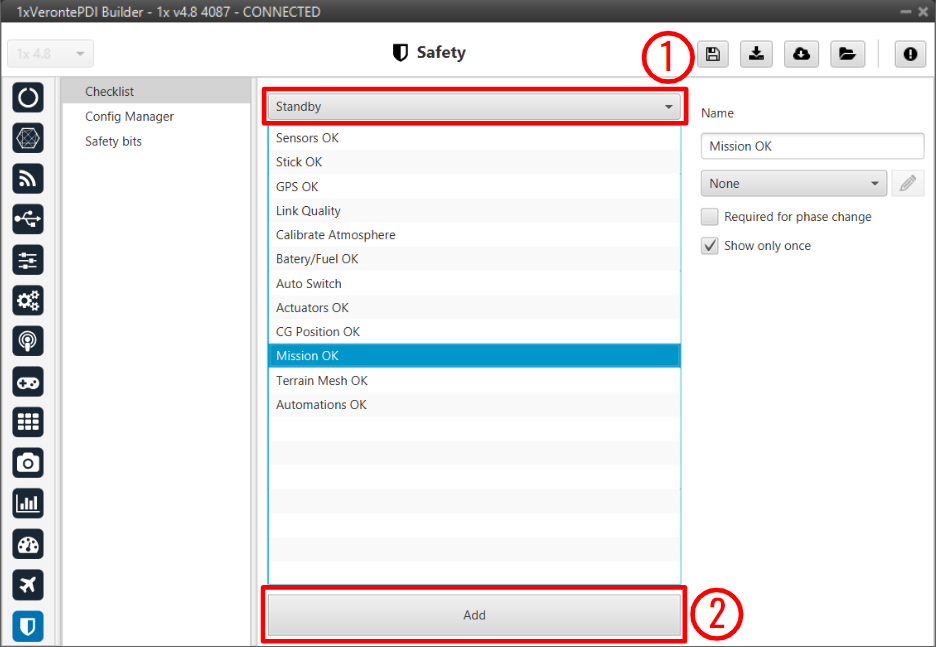
Checklist panel
In (1), the user will find all the phases configured for the operation. In each one of them, new elements for the checklist can be added with the button Add (2). The user can modify the checklist order of the phase by selecting and dragging elements in the list to the desired position.
The configurable parameters for each element are:
Name: The name that will identify the element.
Type: The element chosen from the checklist can be one of the following types:
Calibrate Atmosphere: The user can request the calibration of the atmosphere model.
Calibrate DEM: The user can request the calibration of the DEM.
Command Position: Send to the UAV a position.
Command Yaw: Send to the UAV a yaw angle.
Enter Wind Information: Enter initial values for wind state to the UAV.
In Range Check: Allows checking if a variable is between the range selected.
Error
In order for Veronte Ops to correctly execute this functionality, variables that are added to a checklist as In Range Check must also be added to the mandatory telemetry vector Data vectors.
This is because if they are not added to this telemetry vector, these variables are initialized in Veronte Ops with a value of 0, which in reality may not be the actual value of these variables and may cause confusion in some range.
None: Any action is performed, been just a check for the user to do something external.
Trim arcade: The user can request the stick calibration for arcade commands.
Required for phase change: If enabled, the element must be checked to switch to another phase.
Show only once: If enabled, the check will only appear the first time its phase is executed.
Automatic check: This option is only available when ‘In Range check’ is selected.
An example of ‘In Range Check’ can be shown below:
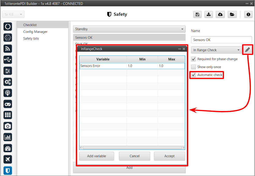
Checklist example
Config Manager
Config Manager avoids the user changing certains parameters, settings or programs of Autopilot 1x. It is shown in the picture below:
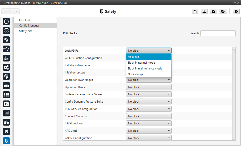
Config Manager panel
The user can choose between:
No block
Block in normal mode
Block in maintenance mode
Block always
Safety bits
In this panel the user can configure 3 different safety bits lists.
The bits included in these lists are added to the set of default system bits that trigger the System error variable, and therefore trigger the FTS. The user can refer to this list of default system bits in the Activation System Error bits section of the 1x Software Manual.
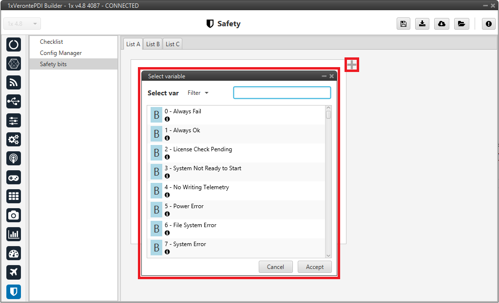
Safety bits panel
By default, there is no bit defined in any Safety bits list. To add them, just press ![]() icon and select the desired bits.
A common user bit to add to these lists is the ‘Sensors Error’ bit, so that if one of the sensors fails, the FTS is triggered.
icon and select the desired bits.
A common user bit to add to these lists is the ‘Sensors Error’ bit, so that if one of the sensors fails, the FTS is triggered.
In addition, the user can switch between the different lists with an action. For more information, see Actions - Automations section of this manual.